Perception Infrastructure
In the B-Human context when we say Perception we mean image processing. The robots other sensors like IMU, joint angles and contact sensors and handled independently.
The perception modules run in the context of the threads Lower and Upper, depending on the used camera. They detect features in the image that was just taken by the camera and can be separated into four categories. The modules of the perception infrastructure provide representations that deal with the perspective of the image taken, provide the image in different formats, and provide representations that limit the area interesting for further image processing steps. Based on these representations, modules detect features useful for self-localization, the ball, and other robots.
Image Format and Color Spaces
The Booster K1 and T1 robots are equipped with different cameras that deliver the captured images in different formats. To be compatible with our previous system, the images are represented in the YUV color space with chroma subsampling in a 4:2:2 format. That means, the horizontal chroma resolution is halved.
As is it often easier to code in terms of luma, hue and saturation, the YUV images are converted to the ECImage1 representation. The ECImage consists of multiple images: the grayscaled image obtained from the Y channel of the camera image, the saturated image and the hued image, containing saturation and hue values for each image pixel respectively.
The hue component H describes the angle of the vector of the U and V components of the color in the YUV color space. Meanwhile, the saturation component S describes the length of that vector divided by the luma of the corresponding pixel. The luma component Y is just the same as it is in YUV. By dividing the saturation by the luma, the resulting saturation value describes the actual saturation of the color more accurately, making it more useful for separating black and white from actual colors. This is because in YUV, the chroma components are somewhat dependent on the luminance.
Camera Matrix
The CameraMatrix is a representation containing the transformation matrix of the camera used in the respective thread that is provided by the CameraMatrixProvider. It is used for projecting objects onto the field. It is computed based on the TorsoMatrix that represents the orientation and position of a specific point within the robot’s torso relative to the ground. Using the RobotDimensions and the current joint angles, the transformation of the camera matrix relative to the torso matrix is computed as the RobotCameraMatrix. The latter is used to compute the BodyContour . In addition to the fixed parameters from the RobotDimensions, some robot-specific parameters from the CameraCalibration (see this section) are integrated, which are necessary, because the camera cannot be mounted perfectly plain and the torso is not always perfectly vertical. A small variation in the camera’s orientation can lead to significant errors when projecting farther objects onto the field.
BodyContour
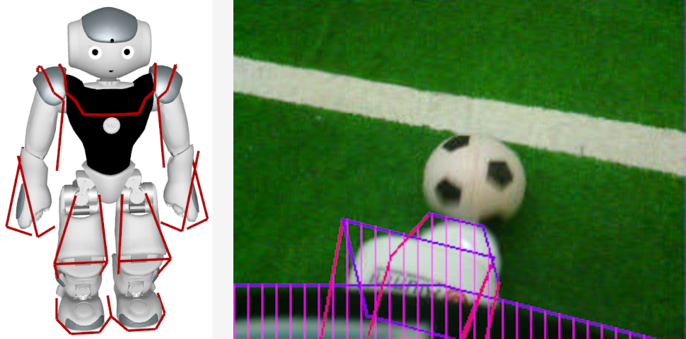
If the robot sees parts of its body, it might confuse white areas with field lines or other robots. However, by using forward kinematics, the robot can actually know where its body is visible in the camera image and exclude these areas from image processing. This is achieved by modeling the boundaries of body parts that are potentially visible 3-dimensionally (figure, left half) and projecting them back to the camera image (figure, right). The part of the projection that intersects with the camera image or above is provided in the representation BodyContour. It is used by image processing modules as lower clipping boundary.
Field Boundary
Given that everything that is relevant to soccer playing robots is located on their field, it makes a lot of sense to limit image processing to the area of the field they are playing on or at least to reject object detections that do not overlap with that field. To be able to accomplish that, the field boundary in the current camera image must be detected.
Detecting the field boundary is one of the first steps in our vision pipeline. Conventional methods make use of a (possibly adaptive) green classifier, selection of boundary points and possibly model fitting. Our approach predicts the coordinates of the field boundary column-wise in the image using a convolutional neural network. This is combined with a method to let the network predict the uncertainty of its output, which allows to fit a line model in which columns are weighted according to the network’s confidence. Experiments show that the resulting models are accurate enough in different lighting conditions as well as real-time capable. The figure shows the detected field boundaries and the predicted uncertainty. For a detailed explanation see 2
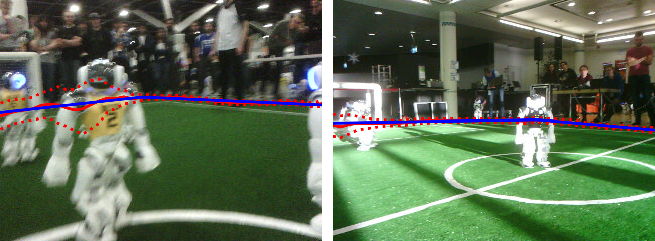
Sample images with the output of the network with uncertainty. The solid red line is the predicted mean, the dotted lines are ±σ intervals, and the blue line is the fitted model.
-
ECImagestood for “extracted and color-classified image”. In earlier version it also contained a fourth image with each pixel classified into one of four color classes. As this relied on manual color calibration, it was removed, the representation's name stayed though. It might be due to be renamed. ↩ -
Arne Hasselbring and Andreas Baude: "Soccer Field Boundary Detection Using Convolutional Neural Networks". In: Rachid Alami, Joydeep Biswas, Maya Cakmak, Oliver Obst (eds) RoboCup 2021: Robot World Cup XXIV. RoboCup 2021. Lecture Notes in Computer Science(), vol 13132. Springer, Cham. https://doi.org/10.1007/978-3-030-98682-7_17 ↩