Shared Autonomy Challenge
The goal of the shared autonomy challenge (see here, section 2) is to take "a step towards [..] enabling robots to play on the same field as agents with human level intelligence". An autonomous robot and a remote-controlled one play against an opposing team. The main research goal is to find the best way to incorporate a human into this setup. One specialty of the challenge is the scoring system: each pass is awarded with one point and a goal is awarded with two points. However, a goal also ends an attempt, which means that playing passes is the most effective way to score as many points as possible.
In the following sections, our approach to the challenge is described, and how to set it up.
Setup
The autonomous robots have odd jersey numbers and the remote-controlled robots have even ones. At the beginning of each half, the remote-controlled robot must always have the greater jersey number, e.g. a pair such as (2, 3) is not allowed. Otherwise, the SetupPosesProvider will assign the wrong starting positions to the robots.
There are three scenarios related to this challenge. For a half in which the team is attacking, the scenario SharedAutonomyAttacker must be deployed. For a half in which the team is defending, SharedAutonomyDefender must be used instead. It is important to deploy the correct scenario, because the setup poses depend on it. The third scenario SharedAutonomyRemote is never deployed to actual robots. It is only used in the simulator for the digital twin that visualizes the information sent by the remote-controlled robot.
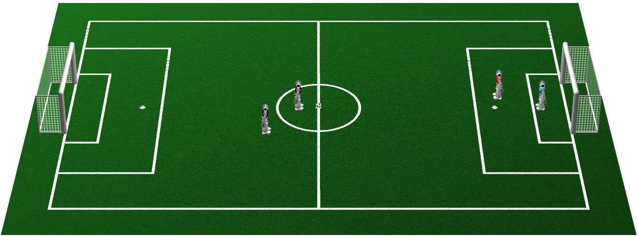
At the beginning of a half, the robots are placed at the positions as shown in the image. For the attacking team (left), the remote controlled robot is placed inside the center circle, because it has to perform the kick-off. For the defending team (right), the autonomous robot must be the goalkeeper, which has to wear a goalkeeper jersey. It is placed at the center circle to win the ball as early as possible.
SimRobot Scenes
There are a number of SimRobot scenes related to this challenge. They are all located in Config/Scenes/OtherScenes:
SharedAutonomyAttacker.ros2: Allows testing an attacking team in simulation. One robot of the black team is autonomous, the other one is remote-controlled. The opponents are just dummies. The user interface for the remote-controlled robot is found under the nameremote.SharedAutonomyDefender.ros2: Allows testing a defending team in simulation. The blue goalkeeper is autonomous. The red remote-controlled robot is the field player. Otherwise everything is the same as above.SharedAutonomyGame.ros2: The scene contains both the attacking and the defending team. In this case, there are two user interfaces for the two remote-controlled robots, calledremoteAttackerandremoteDefender.SharedAutonomyRemote.ros2: This scene provides the user interface for controlling a physical robot. The control PC must be on the same network as the remote-controlled robot. The remote-controlled robot must not be in the unstiff state for the scene to initialize properly.SharedAutonomyReplay.ros2: A scene for replaying logs recorded by the remote-controlled robot. The player number in the log file must match the rules for being the remote-controlled robot. Otherwise, the code might not initialize correctly.
Scripts
The two scripts Make/Common/sacRed and Make/Common/sacBlack (Make/Windows/sacRed.cmd and Make/Windows/sacBlack.cmd on Windows) can be used to start SimRobot with the scene SharedAutonomyRemote.ros2. Both scripts set the jersey color of the robot shown in the 3D view to the one mentioned in their names. By default, a robot from the own team (the team number defined in Config/settings.cfg) is remote-controlled. By passing a team number as an argument to the scripts, a robot with a different team number can be controlled instead. If the latter is not required, the scripts can directly be executed from the file manager of the graphical user interface without opening a terminal application first.
Communication
The communication between the host PC and the controlled robot uses UDP packets. The host PC broadcasts its packets on the port 10100 + team number. The controlled robot listens on this port and sends back its packets to the origin of the broadcast, unless it is in the unstiff state. This approach has the advantage that the host PC and the controlled robot automatically find each other, i.e. it is possible to switch to a different host PC or controlled robot mid-challenge without changing the configuration. To avoid flooding the network, packets are only sent at 10 Hz.
It both directions, the network packets contain a single message queue. The host only sends the JoystickState and the SharedAutonomyRequest. The former just contains which buttons and sticks are pressed on a joystick or gamepad. The latter contains a command, e.g. where to go or where to kick. Only one of these two representations is actually used, depending on whether mouse and keyboard control or gamepad control is activated. The controlled robot sends a message queue that basically emulates part of a log file. It contains single frames for either the thread Upper or Lower and for the thread Cognition. These frames are directly fed into the digital twin of the controlled robot. They contain highly compressed JPEG images, the game state, models of the controlled robot's position, the teammate's position, the ball both as seen by the controlled robot and its teammate, and the obstacles the controlled robot sees. To animate the digital twin realistically, its joint angles and its inertial measurements are also sent. Finally, the SharedAutonomyRequest is transmitted back as well, because in case of the gamepad control, it is created on the controlled robot. It is also enriched by the information, whether the teammate is currently playing the ball.
Behavior
Tactics
Three tactics are defined for this challenge:
- Attacking (
t011): The autonomous robot either positions itself around the halfway line or deeper into the opponent half, depending on the position of the remote-controlled robot. It tries to score a goal if the indirect kick rule allows it. - Defending (
t100): The autonomous robot plays as a goalkeeper, defending its goal. - Passing (
t020): The autonomous robot tries to stay on the height of the ball along the field, so both players can pass the ball back and forth. The remote-controlled robot can decide where this passing takes place by playing the ball to the desired area. As passes only count if the ball travelled more than 1 m, the autonomous robot tries to position itself at least 1.5 m away from its teammate.
Strategies
Two strategies are defined, one for playing as the attacking team and one for playing as the defending team:
- Attacking: In this strategy, the passing tactic is the default. The operator can manually switch to the attacking tactic.
- Defending: Here, the defending tactic is the default, and it can manually be switched to the passing tactic.
Manual Tactic Switching
The manual tactic switching was implemented through the communication channel that is used for implementing the indirect kick rule. When being the attacking team, the remote-controlled robot simply hides the fact that it has already played the ball, forcing its teammate to pass, because scoring would not be allowed yet. When playing as the defending team, the same channel is used, but the autonomous robot knows that it is not allowed to score a goal and simply uses the information that its teammate pretends to have touched the ball to switch to the passing tactic.
2D View
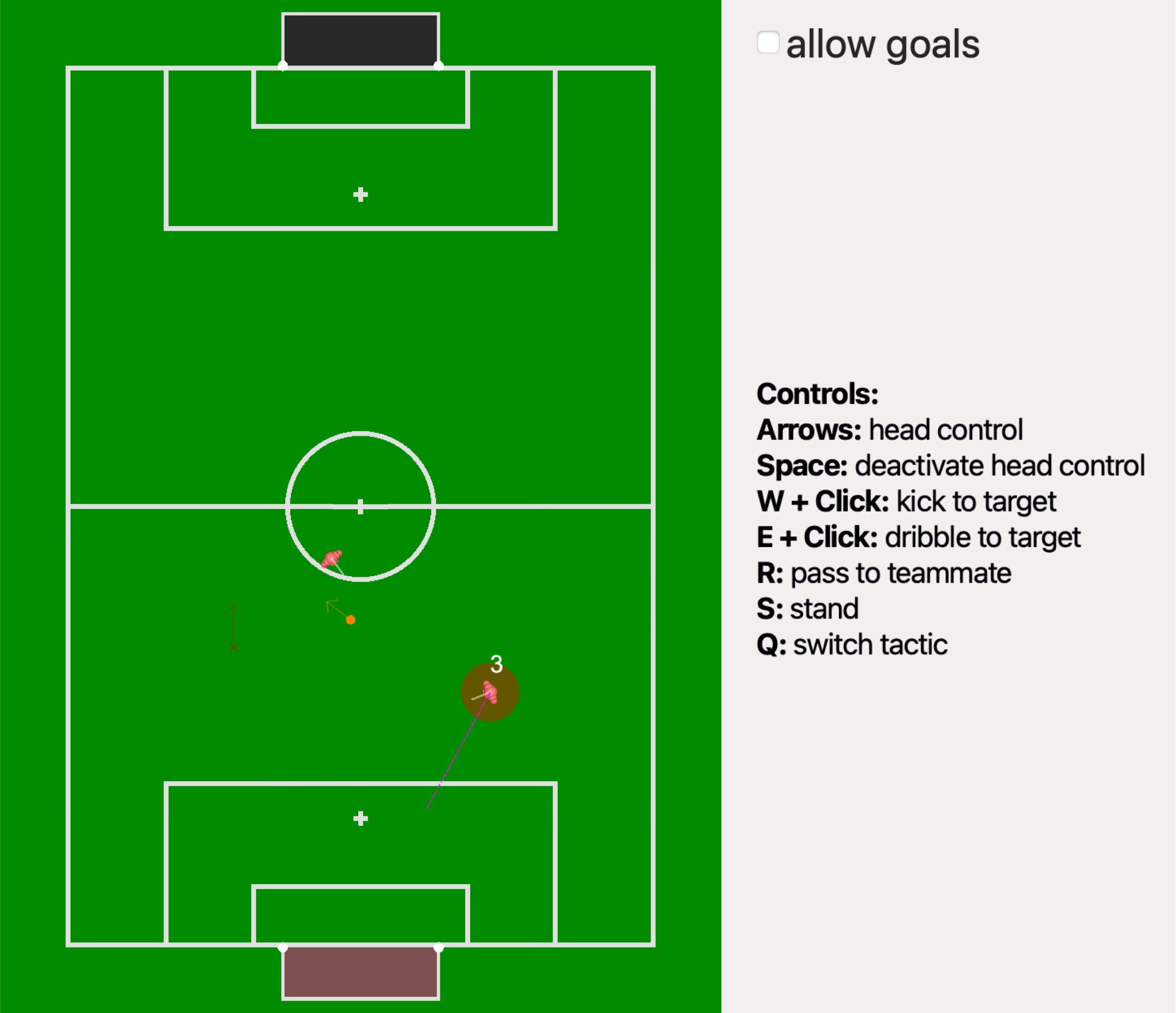
The 2D view is basically B-Human's normal field view, but rotated by 90° so the opponent goal is always depicted at the top. It shows the positions of the remote-controlled robot, the team mate (surrounded by a team-colored circle), and opponent robots (colored boxes), as well as the position of the ball (orange circle). The position the teammate plans to walk to is marked by a cross that is connected to that teammate. In addition, a cross with an arrow marks the position the remote-controlled robot will walk/kick/dribble to. Next to the field view, the currently selected tactic is marked and a legend explains the actions that can be selected.
Mouse and Keyboard Control
Robot Actions
The robot is controlled through a combination of mouse clicks and key presses:
- By clicking onto the field view, a walk target is selected. A direction at the target can also be set by dragging into the desired direction while the mouse button is clicked. However while walking, the robot will always face the ball if its position is known.
- If the key
Wis pressed while clicking, the kick target is set, i.e. the robot will attempt to kick at this position. - If the key
Eis pressed while clicking, the robot will dribble to this position. - By just pressing
R, the robot will pass to its teammate. - Pressing
Sresults in the robot standing still.
For the keys R and S to have an effect, the 2D view must be the active view. Each of these modes stays active until a new one is chosen.
Head Control
The robot's head can be controlled through the four arrow keys. The longer an arrow key is pressed, the further the head turns into that (pan/tilt) direction. Pressing the space bar returns to automatic head control.
Tactic
The check box next to allow goals selects the current tactic (see here). It can also be toggled by pressing the key Q. If playing as attacking team, it is selected whether the autonomous robot should try to score a goal or not. When playing as defending team, allow goals means that the autonomous robot acts as a field player instead of a goalkeeper. It does not actually try to score a goal.
3D View
The 3D view uses a standard feature of SimRobot, which allows to display individual objects from the scene graph in a separate view. The view has to be configured the first time it is used. SimRobot will then remember this configuration when the same scene file is opened again.
Setting up the View
These are the steps to setup the view:
- From the Scene Graph, open
RoboCup.puppets.remote(or bothRoboCup.puppets.remoteAttackerandRoboCup.puppets.remoteDefenderin case of the sceneSharedAutonomyGame.ros2). - In the view that opens, select
Origin|Object Positionfrom the popup menu. - Also select
Drawings Rendering|Occlusion|Transparentfrom the popup menu. - Use the mouse to place and zoom the robot similar to the screenshot shown below. You can drag around the scene, rotate it by pressing
Shiftwhile dragging, and use the mouse wheel, two-finger-dragging, or a pinch gesture to zoom.
Information Shown in the View
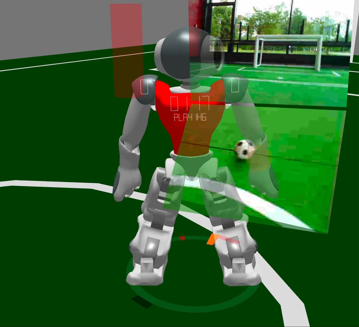
The robot shown in the view mimics the motion of the remote-controlled robot. Two rectangles show the camera images taken by the robot in the direction it is currently looking. The robot's estimated position on the field is shown by drawing the entire field relative to the robot. The robot's ball model is visualized as a transparent orange sphere. Other robots are shown as transparent cylinders in the jersey color of the player (if it was detected correctly). The teammate's walk target is shown as a jersey-colored cross on the field.
Please note that the perspective of the camera images and the 3D drawings is not the same. Therefore, objects might appear in a different location in one of the images than in the 3D visualization.
The robot's feet are surrounded by a ring that indicates the directions to different objects on the field. The direction to the ball is shown in orange. The directions to other robots are depicted in their jersey colors. Just outside the ring, the directions to the two goals are shown, again marked by the team colors. The larger a ring segment is, the closer the object.
On the shoulders of the robot, the current score is depicted (left: goals scored; right: goals conceded; these are actually points instead of goals in simulation). Next to the goals scored, a plus sign is shown if the alternate tactic is active (see below). At the top of the jersey, the remaining time in the half is shown. Below, either the current game state, the current set play, or the fact that the robot is penalized can be seen. During a set play and the first 10 seconds after a kick-off as well as when the robot is penalized, the remaining time is shown below. In case of a set play or a kick-off, an arrow next to the remaining time in the half indicates the attacking team (left: own team; right: opponent team). If the teammate is playing the ball, an arrow pointing downward is shown, indicating to back-off from the ball.
Gamepad Control
The remote control with a gamepad is inactive by default. To activate it, the kick mode button (see below) must be pressed once on the gamepad. The gamepad control is meant to be used in combination with the 3D view, i.e. from an egocentric perspective of the robot.
Control Modes
The gamepad control is split into four different control modes. The walk mode is the default and the other three ones can be activated by continuously pressing a specific button. The use of the different analog sticks and buttons is shown in the figure below. The buttons on the right are often numbered and their layout might differ. In that case, refer to the numbers written behind the modes.

- In the walk mode, the left analog stick is used to walk forward and sideways with the robot. The further the stick is pressed, the faster the robot moves. The robot is turned by pressing the right stick left or right. Again, the turn speed is proportional to how far the stick is pressed. Please note that walking against the ball does not count as having intentionally played the ball, as required by the indirect kick rule.
- In the pass mode, the robot tries to pass to the teammate.
- In the dribble mode, the robot dribbles in the direction that is indicated with the left analog stick. The 3D view shows this direction as an orange arrow originating from the position of the ball. If the analog stick is not moved, the robot keeps dribbling in (globally) the same direction.
- In the kick mode, the robot tries to kick to a point that is indicated through the left analog stick. The target position is indicated by an orange arrow. Again, if the analog stick is not moved after a target was picked, the target position stays the same.
By default in pass mode, dribble mode, and kick mode, the robot is automatically switching to a different action if the requested one cannot be executed. For instance, it might duel with an opponent for the ball. However, the original action can be enforced by pressing the button that is integrated into the left analog stick.
Head Control
The head can be moved through the vertical axis of the right analog stick (tilt) and the analog triggers or the shoulder buttons of the gamepad. If the gamepad is equipped with analog triggers, they can be used to gradually set a pan direction for the head. With the digital shoulder buttons, only the maximum pan angle can be commanded. Since the head only pans with a certain speed, this still allows to shortly look into a certain direction and then release the button to turn back.
If neither the buttons nor the vertical axis of the right analog stick are pressed, the robot performs its default head motion.
Standing and Sitting Down
For convenience, it is also possible to let the robot stand or sit down. This is achieved with two buttons on the directional pad. Once the robot is standing, the stand button toggles between the normal stand and the high stand.
Both standing and sitting can be exited by starting to walk in walk mode.
Tactic
Pressing the tactic button switches between the two available game tactics (see here). When playing as the attacking team, either the ball is passed back and forth between the two players or the team tries to score a goal. When playing as the defending team, the autonomous player either behaves as a goalkeeper or a field player.
By default, the attacking team does not try to score and the autonomous player of the defending team plays as a goalkeeper. Pressing the tactic button once switches to the other tactic. Pressing it again will switch the tactic back.
Console Commands
A console command was added for this challenge and optional arguments were added to other commands. These changes are not listed in the section about console commands, because they will probably be removed again after this year's code release:
sl <name> [ (<file> | remote) ...: The command that is normally used to start replaying a log file is reused to create a digital twin for a remote robot. When replaying a log file, the data recorded in the file is fed into an instance of the B-Human framework. With the optionremote, no log file is opened. Instead, the data received from the remote robot is fed into a framework instance. This allows to create 2D and 3D drawings from the representations that are received using the drawing code that is already available in the framework.sac [view] ( local <team number> | remote <team number> <broadcast> ): Starts the connection to a remote controlled robot. This can either be a simulated (local) robot or an actual (remote) one. In both cases, the team number is specified. For a real robot, the broadcast address that robot will listen to has to be specified as well. If the optionviewis given, a 2D view is added to SimRobot.gc ... | competitionTypeSharedAutonomyChallenge: Activates the competition type for the challenge in SimRobot's GameController. The mode is fully functional, i.e. it implements most of the rules of the challenge correctly. The only exception is that the defending team cannot score an own goal if the attacking team has only touched the ball once, because the simulated GameController does not distinguish between intentional kicks and a ball that just bounces of, but was kicked by another robot. In contrast to the real GameController, this one actually counts points rather than goals.vf [force] ...: The integration of the 2D view into SimRobot is a little bit hacky. As a result, the view will register an incomplete field view when it is created as part of SimRobot's layout restoration when a simulation scene is opened. The optionforcelets the commandvfaccept that the view it should now create is already partially registered.
Results
B-Human played five games and won all of them. Overall, we scored 52 points (all through passes), while the other eight participating teams together only scored 20 points. During the competition, the mouse and keyboard interface was used, together with both the 2D view and the 3D view. In our first game, when playing as defending team, our autonomous robot started as a real goalkeeper, i.e. protecting its goal. In all other games, the goalkeeper started at the center circle, playing the field player (passing) tactic right from the beginning. So we basically only played the passing tactic, making tactic switching unnecessary (not entirely, because the defending tactic is still the default when being the defending team).